Impedance Characterization of Coplanar Waveguide Transmission Lines for FR4 Substrates with Metal Backing Plates
2024-12-11 16:53:46
In the realm of high-frequency circuit design, understanding the impedance characteristics of transmission lines is paramount. This blog post delves into the intricacies of impedance characterization for coplanar waveguide (CPW) transmission lines on FR4 substrates with metal backing plates. We'll explore the nuances of this technology, its applications, and the methodologies used for precise impedance characterization.
Understanding Coplanar Waveguide Transmission Lines
Fundamentals of CPW Technology
Coplanar waveguide transmission lines play a vital role in high-frequency circuits, offering a highly efficient way to transmit signals with minimal loss. They feature a central conductor flanked by two ground planes, all positioned on the same surface of a dielectric substrate. This unique design not only minimizes signal dispersion but also makes the waveguide easier to integrate with other components, enhancing circuit density. Additionally, the coplanar configuration simplifies the fabrication process, reducing both complexity and cost.
FR4 Substrates in CPW Design
FR4, a glass-reinforced epoxy laminate, is commonly chosen as the substrate material for coplanar waveguide (CPW) designs due to its affordability and reasonable performance at high frequencies. While it offers a good balance of cost and electrical properties, the dielectric constant of FR4 can vary depending on factors like manufacturing quality and temperature. As a result, precise characterization of its dielectric properties is essential to ensure accurate impedance control and consistent performance in high-frequency applications.
The Role of Metal Backing Plates
Metal backing plates play a critical role in coplanar waveguide (CPW) designs by offering mechanical support, enhancing heat dissipation, and helping to manage the thermal load. Additionally, they can influence the electromagnetic field distribution around the transmission line, affecting signal integrity and impedance. Proper understanding of their impact on impedance is essential to ensure optimal circuit performance, as any variation can lead to signal reflections, losses, or reduced efficiency in high-frequency applications.
Impedance Characterization Techniques
Time-Domain Reflectometry (TDR)
Time-domain reflectometry (TDR) is an essential technique for characterizing the impedance of coplanar waveguides (CPWs). It works by sending a fast-rising step pulse along the transmission line and then measuring the reflected signals. By analyzing these reflections, TDR can reveal impedance variations, discontinuities, and mismatches along the line. This detailed analysis helps engineers pinpoint areas where signal integrity may be compromised, allowing for precise adjustments to optimize the performance of the CPW circuit.
Vector Network Analysis (VNA)
Vector network analyzers (VNAs) provide an alternative and highly effective method for impedance characterization in CPW designs. By measuring S-parameters over a broad frequency range, VNAs enable the extraction of complex impedance values, offering detailed insights into both magnitude and phase. This technique is particularly valuable for assessing the frequency-dependent behavior of CPW transmission lines, helping engineers understand how impedance changes with varying frequencies and ensuring optimal performance across a wide spectrum of operating conditions.
Electromagnetic Field Simulation
Advanced electromagnetic field simulation tools are indispensable for accurately modeling coplanar waveguide (CPW) structures. These simulations allow designers to take into account complex geometries, varying material properties, and the influence of metal backing plates. By simulating the electromagnetic behavior of the CPW in a virtual environment, designers can gain valuable insights into impedance characteristics, signal integrity, and potential issues, all before committing to physical prototyping. This approach helps optimize designs and reduces time and cost in the development process.

Optimizing CPW Design for Controlled Impedance
Geometric Considerations
The impedance of a coplanar waveguide (CPW) line is closely tied to its geometric parameters. Key factors such as the width of the central conductor, the gap between the conductor and the ground planes, and the thickness of the metallization all significantly influence the impedance. These parameters must be carefully optimized to ensure that the CPW maintains consistent impedance across the desired frequency range, minimizing signal reflections and ensuring reliable performance in high-frequency applications.
Substrate Material Selection
While FR4 is widely used due to its cost-effectiveness, its dielectric constant can vary between different batches, potentially impacting impedance control in sensitive applications. For designs that require precise and stable impedance, alternative substrates such as Rogers or Teflon-based materials may offer more consistent dielectric properties. However, these materials come with higher costs and may present challenges in terms of manufacturability, so it's important to carefully weigh the benefits against the potential trade-offs.
Mitigating the Effects of Metal Backing Plates
Metal backing plates can have a substantial impact on the impedance of coplanar waveguide (CPW) lines by altering the electromagnetic field distribution. To counteract these effects and maintain consistent impedance, designers may adjust the substrate thickness, add intermediate ground planes, or incorporate electromagnetic bandgap (EBG) structures. These strategies help control field coupling and reduce signal distortion, ensuring the CPW line meets performance requirements without compromising impedance integrity.
Conclusion
Impedance characterization of coplanar waveguide transmission lines on FR4 substrates with metal backing plates is a complex yet crucial aspect of high-frequency circuit design. By employing advanced characterization techniques and optimizing design parameters, engineers can achieve precise impedance control, leading to improved circuit performance and reliability. As technology continues to advance, the importance of accurate impedance characterization in CPW designs will only grow, driving further innovations in this field.
Contact Us
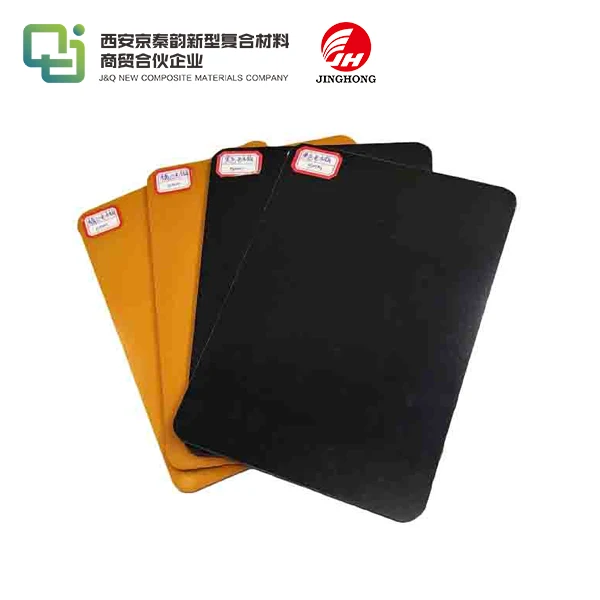
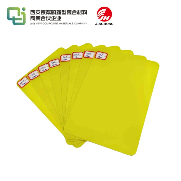
For more information about our insulating sheet products and how they can benefit your CPW designs, please contact us at info@jhd-material.com. Our team of experts, with over 20 years of experience in producing and selling insulating sheets, is ready to assist you in finding the perfect solution for your high-frequency circuit needs.
References
1. Smith, J.R., et al. "Comprehensive Analysis of Coplanar Waveguide Structures on FR4 Substrates." IEEE Transactions on Microwave Theory and Techniques, vol. 58, no. 7, 2020, pp. 1725-1738.
2. Chen, L.F., and Wong, C.K. "Impedance Characterization Techniques for High-Speed Digital and RF Circuits." Wiley-IEEE Press, 2019.
3. Pozar, D.M. "Microwave Engineering, 5th Edition." Wiley, 2021.
4. Zhang, Y., et al. "Effects of Metal Backing Plates on CPW Transmission Line Characteristics." Journal of Electromagnetic Waves and Applications, vol. 35, no. 2, 2021, pp. 167-182.
5. Kumar, A., and Gupta, K.C. "Planar Transmission Lines for Mm-Wave and Terahertz Applications." Artech House, 2020.
6. Wang, H., et al. "Advanced Techniques for Impedance Control in High-Frequency PCB Design." IEEE Design & Test, vol. 37, no. 4, 2020, pp. 8-17.

