Discussion on Structure and Process Design of High Voltage Pulse Transformer
2022-10-09
High voltage pulse transformers are widely used in radar, high-energy physics, environmental protection and dust removal, linear electron accelerator and other technical fields. As the voltage becomes higher and higher (generally from tens of kilovolts to hundreds of kilovolts), the requirements for waveform become stricter and stricter, and the project implementation becomes more and more difficult. For the successful development of high-voltage pulse transformer, the design and calculation guarantee is on the one hand, and the structural design, process design and process treatment in the processing are also crucial. For high-voltage pulse transformer, sharp corners or burrs at fine points can make the transformer break down during operation, and the transformer cannot work normally due to damage. The following will introduce the problems that need to be considered and noticed in the implementation process from the aspects of structure and process.
1. Structural design
a) Winding structure
The design criterion of pulse transformer is to ensure the maximum energy transmission coefficient and the minimum pulse waveform distortion for the load, so it is necessary to obtain appropriate leakage inductance and distributed capacitance parameters through reasonable design. The form of the winding largely determines the distribution parameters (leakage inductance and distributed capacitance) of the pulse transformer. There are three common winding structures: cylindrical winding, circular winding and ring winding. The specific structure should be comprehensively considered.
The engineers who design the pulse transformer know that the leakage inductance is one of the important parameters of the pulse transformer, and the leakage inductance directly affects the leading edge characteristics of the output pulse waveform. To reduce leakage inductance, in addition to reducing the number of primary turns and insulation distance, it is one of the more effective methods to increase the number of alternating winding groups M of the primary winding. However, for hundreds of kilovolt high-voltage pulse transformers, the alternating winding of the primary winding is difficult to achieve the withstand voltage insulation treatment, which increases the risk of voltage withstand breakdown of the transformer. The interlayer insulation thickness of ordinary pulse transformer winding is constant. Generally speaking, the primary winding is wound one layer, and the secondary winding is wound one layer or several layers. The insulation distance between the primary stages is determined by the highest voltage applied between them.
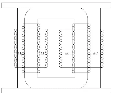
In order to meet the requirements of pulse high-voltage power supply for low leakage inductance and high withstand voltage of pulse transformer, the windings need to be reasonably configured. We generally use cylindrical windings, and the secondary windings use asymmetric high-voltage coil structure, that is, the turns of the secondary coils are evenly distributed on two magnetic poles of the magnetic core. According to the principle that the output voltage increases in the same proportion with the number of secondary turns, The insulation distance △ 1 of the first half turn coil (referred to as the low-voltage package for short) is used to design the high-voltage package △ 2 × 1, which saves the width of the magnetic core window and the cost of the magnetic core. While ensuring the insulation withstand voltage strength, it also reduces the leakage inductance of the pulse transformer, which not only improves the output waveform, but also improves the waveform transmission efficiency. The asymmetric coil structure is shown in Figure 1.

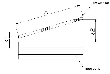
The other type of winding structure is the tapered winding, which is a novel structure and is generally used in situations where the output pulse voltage is 250kV. It makes use of the characteristic of equipotential gradient drop between the windings of the pulse transformer, and distributes the main insulation structure according to the equipotential gradient, so that the magnetic circuit length of the iron core can be reduced and the volume of the iron core can be reduced accordingly when the section of the iron core is unchanged. It can also reduce the average turn length of the winding. Compared with the winding with rectangular window, the leakage inductance is reduced by about 1/2. The distributed capacitance increases little. Due to the high transformation ratio, the total capacitance (including load capacitance) only increases by 3.5%, while it decreases by about 23% in direct proportion to the leading time? Therefore, the tapered winding structure can be used to design a pulse transformer with small volume, light weight and good output pulse waveform.
See Figure 2 for the structure diagram of tapered winding

b) Insulation structure design
i. Primary lead out
Generally, the secondary output pulse voltage of the high-voltage pulse transformer is more than 100 kV. The transformer structure is designed as the upper and lower platens are compressed with four screws, and the lower platens are fixed with reserved installation holes. The secondary skeleton shall be completely overhead with the primary winding, and the overhead skeleton shall be positioned in the limit slot of the upper and lower pressing plates to ensure the insulation distance with the primary coil, so as to improve the insulation reliability of the transformer. The primary current of the high-voltage pulse transformer is very large, and the peak current is generally thousands of amperes. The lead out must be connected with thick copper bars. In order to increase the distance between it and the secondary high-voltage winding, the lead out should be separated as far as possible. We use the in-line copper bars to lead out directly through the upper platen, and accurately open a thin and long outlet slot on the upper platen, which not only increases the distance between the primary lead out and the secondary lead out, but also facilitates the connection during the assembly of the pulse power supply.
ii. Insulating material
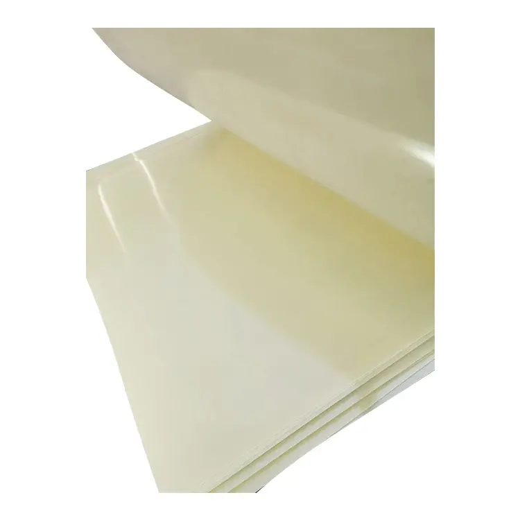
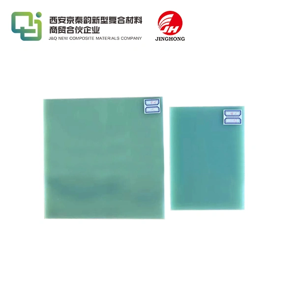
The secondary output voltage of the pulse transformer is very high. Considering the design margin, ignition and other abnormal conditions, the insulation and withstand voltage of the secondary of the pulse transformer to the primary and ground are generally designed according to the output voltage requirements of 1.2 to 1.4 dong. The primary coil is of overhead structure, and the main insulation material is 45 # transformer oil. The overhead insulation distance at the highest voltage difference between the primary and secondary windings is about 5kV/mm. The secondary skeleton material of conventional high-voltage pulse transformer is generally made of 3240 epoxy sheet. The surface of the skeleton is flat. When the coil is wound, the inter turn wires are closely connected, and the winding process is difficult. We choose EPGC 201 series epoxy board as the secondary skeleton material. Compared with the conventional 3240 epoxy resin sheet, EPGC epoxy board is more dense, not easy to delaminate, and has more reliable insulation performance under high voltage electric field.

As the output voltage of the transformer is high, the transformer transformation ratio is also large, that is, the number of turns of the secondary winding is also large. We slot the secondary skeleton according to the number of turns, and fix the limit value of each turn of the secondary skeleton to ensure the inter turn distance, so as to minimize the inter turn withstand voltage problem caused by production operations.
In order to avoid the transformer breakdown problem that may be caused by sharp corners or burrs of the framework and installation structural members, we require that all the corners of the structural members be chamfered with R Υ To prevent high-voltage tip discharge and scratch on the insulation layer of the wire during the winding production process.
iii. Multipoint grounding of iron core
In order to make the pulse transformer more reliable when working at high voltage and avoid the suspension and electrification of the iron core when working at high voltage, the iron core is generally grounded separately. After multipoint grounding, the iron core is led out to the four metal pull rods installed and connected together with the grounding wire to ensure that all metal parts are on the same ground.
2. Process planning
Most high-voltage pulse transformers use transformer oil as the main insulating material. Theoretically, the withstand voltage strength of transformer oil is very high, up to 55kV/2.5mm (a standard oil distance). However, in practical engineering applications, the withstand voltage of transformer oil mainly depends on its insulation treatment process and vacuum oil filling process, which are described below.
a) Transformer oil insulation treatment process
There are 25 # transformer oil and 45 # transformer oil. The main difference is that the low temperature freezing point is different. We generally use 45 # transformer oil. The transformer oil shall be treated before each use. The breakdown voltage of the treated oil shall not be less than 50kV/2.5mm standard discharge. The vacuum oil filling of the high-voltage pulse transformer can only be carried out after the inspection is qualified. Precautions for transformer oil insulation treatment mainly include:
i. The workshop shall be clean, dry, dust-free and well ventilated.
ii. Containers for transformer oil and equipment for oil treatment (such as filter press, vacuum cooker, etc.) shall be clean, dry and sealed.
iii. Pay attention to prevent water drops, cotton yarn fibers or other dirt and impurities from falling into the transformer oil. Do not talk to the transformer oil to prevent saliva from splashing into it.
iv. The compressor oil is vacuum dried in a vacuum pan, pressurized and heated, with a temperature of 85 ± 5 ℃ and a general holding time of 12 hours. The holding time is determined according to whether the breakdown voltage test of the oil sample is qualified.
b) Vacuum oil filling process
In order to ensure that the high-voltage pulse transformer produced can meet the designed withstand voltage strength, the transformer oil shall be injected in a vacuum environment. Generally, non vacuum oil filling is not allowed. It is impossible to remove the bubbles in the oil filling coil without vacuuming, which will greatly reduce the insulation performance of the transformer.
i. Drying: The cleaned transformer shall be dried for 4~8 hours in a 110 ± 5 ℃ blast thermostatic oven (depending on the size and weight of the element).
ii. Insulation resistance test: without taking out the oven, use a 1000V megger to measure the insulation resistance between windings of any transformer and between windings and shells, which should not be less than 100 megohms (note that the temperature should be 110 ± 5 ℃). If the insulation resistance is lower than 100 megohms, continue to dry until it exceeds this value.
iii. Vacuum oil filling: the vacuum drying temperature is 100~105 ℃, the residual pressure is less than 5 mm mercury column, and the time is 6~10 hours. The qualified transformer oil shall be pumped, and the oil level shall cover the transformer about 40mm.
3. Concluding
The successful production of a high-voltage pulse transformer requires not only careful and detailed theoretical design to ensure its withstand voltage strength, but also detailed planning on the structure and process. Only by handling the details of the process operation during the production process, can the withstand voltage and insulation performance be guaranteed. Therefore, the process problem is very important, and every engineer must pay attention to it.


